n
anonymousdoortablet/dthelp.nsfremote-led-hardware
Protected content
| 273pages | Our help system contains many pages and videos for you to consume. This includes the complete information on how Door Tablet works, all its features and options, and of course the many benefits for your business. Door Tablet School offers many videos too. |
|
 |
| 
Click on images to see them in full screen
122B00C8E7FCAD6F80258C270047611ERemote LEDs Hardware
Door Tablet offers packages that combine the Device Hub and other electronics. This includes devices that do not need to be away from the Device Hub or exposed to the inner part of a room. One good example of this is a combined package of Device Hub and the Remote LED.
To learn about the software you need and how to configure the system please see here 
Learn more about the device hub here .
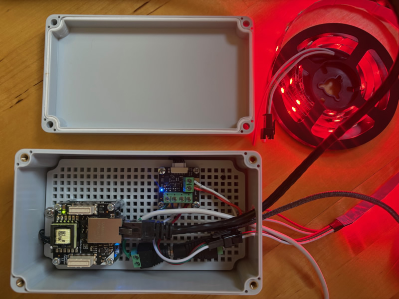
In the package shown here you can see the Device Hub and the LED electronics combined.
VIDEO: Configuring Door Tablet's External LED System
Note: in the image below, opposite the green connectors, the cream rectangle is the socket that provides the connection to the Device Hub. Door Tablet uses that connection to drive the colour changes in line with Meeting Room status.
Features
- Controls up to 2048 RGB or 1536 RGBW LEDs
- Update rate of up to 100Hz for each LED possible
- Supports multiple drivers
Technical Specification
| Property | Value |
| Drivers | WS2801, WS2811, WS2812/SK6812 (NeoPixel RGB), WS2813, WS2815, SK6812RGBW (NeoPixel RGBW), LPD8806 and APA102 (DotStar) |
| Current Consumption | 64mW (12.8mA at 5V) |
| Resolution | 8bit per LED |
| Maximum LEDs | 6144 (2048 RGB or 1536 RGBW LEDs) |
| Maximum Update Rate | 100 updates per second |
| Dimensions | 30 x 30 x 12mm |
| Weight | 8.1g |
Supported LEDs
The LED Strip Bricklet 2.0 supports LED strips and pixels equipped with the WS2801, WS2811 or WS2812, SK6812 (NeoPixel RGB), SK6812RGBW (NeoPixel RGBW), LPD8806 and APA102 (DotStar) driver ICs. Driver ICs refers to any of these chips.
You have to configure which of these driver chips you want to use with the Brick Viewer or the set_chip_type() function of the LED Strip Bricklet 2.0.
The driver ICs can control up to four LEDs independently. Typically a RGB(W) LED combined in one package is used. It is controlled over a three or two wire chained data bus with clock, data signal and ground as voltage reference. Each Driver has a bus input connected to a controlling device such as the LED Strip Bricklet 2.0 or to a driver predecessor and a bus output which can be connected to a subsequent LED driver. Since it is a chained bus, a single bus output has to be connected only to a single bus input. The bus is indexed beginning with the first LED driver on the LED Strip Bricklet 2.0 (API index 0).
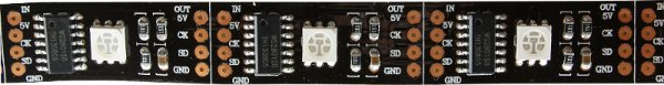
The above picture depicts a typical WS2801 LED strip. You can see each module equipped with one WS2801 chip and a connected RGB LED. Recognise the signal labels for input (IN) and output (OUT): 5V, CK (clock), SD (serial data) and GND. In contrast to the WS2801, the WS2811 and WS2812 driver chips don't have a clock signal.
Connectivity
The following image depicts the interfaces of the LED Strip Bricklet 2.0.
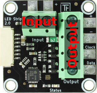
As described in the section above, the Bricklet supports LED strips and pixels with WS2801, WS2811, WS2812, SK6812 (NeoPixel RGB), SK6812RGBW (NeoPixel RGBW), LPD8806 and APA102 (DotStar) driver. The terminal labelled with "Output" has to be connected with the input of the first LED driver.
The output terminal consists of four signals:
- "DAT" is the data signal line to the LED driver chip. It has to be connected to the data input of the first driver chip. Unfortunately, there is no general label on LED pixels or on LED strips for this input. Sometimes the signal is marked with SD (Serial Data) or DI (Data Input). It is also possible that the input of the pixel or strip is not marked, but the output is marked (DO, Data Output). If the output is marked, the non-marked other side has to be the input.
- "CLK" is the clock signal line to the driver chip. It has to be connected with the clock input of the first LED driver chip. This input is typically labelled with CLK, CK or CI (Clock Input). If only the output is labelled it can be labelled with CO (Clock Output).
The WS2811, WS2812 and SK6812 chips don't have a clock signal, leave the "CLK" terminal unconnected form them.
- "-" is the ground signal line. Ground is necessary to give a reference for the DAT and CLK signals.
- "+" is the supply voltage output. It is connected to the "+" signal of the "Input" terminal and should not be used to power LED Strips or pixels. Leave it unconnected and power the connected strip or pixels directly from your supply.
The input terminal consisting of two signals:
- "+" voltage supply input. It can be connected to the power supply for the LEDs to measure the supplied voltage. If you don't need this feature you can leave it unconnected.
- "-" is the ground input. It is internally connected with the "-" ground of the "OUTPUT" terminal.
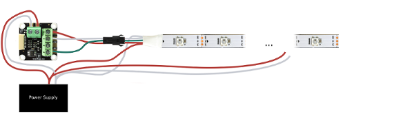
LED Strips without Clock Signal (e.g. WS2812B)
There is no general colour code for LED strips. Sometimes the colour codes are against any agreements. In this WS2812B LED strip example the red wire is 5V, green is data the white wire is ground.
Connect data of the first strip to the LED Strip Bricklet 2.0 and connect ground of your power supply to it. Pay attention to connect the data input of the first strip to the data output of the LED Strip Bricklet 2.0.
If you want to measure your supply voltage connect 5V to the Bricklet, too. You can connect more LED strips to the first strip in series.
It is not sufficient to power the LED strips only at one point. We recommend to feed power to the strip at least every two meters. This can be done by connecting a cable between the strip and the power supply for each supply point. This will reduce the resistance and minimise the conduction losses. See the following image as an example for it.
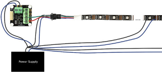
 LED Strips with Clock signal (e.g. WS2801)
There is no general colour code for LED strips. Sometimes the colour codes are against any agreements. In this WS2801 LED strip example the black wire is 5V, green is clock, red is data and the blue wire is ground.
Connect clock and data of the first strip to the LED Strip Bricklet 2.0 and connect ground of your power supply to it. Pay attention to connect the clock and data input of the first strip to the clock and data output of the LED Strip Bricklet 2.0.
If you want to measure your supply voltage connect 5V to the Bricklet, too. You can connect more LED strips to the first strip in series.
It is not sufficient to power the LED strips only at one point. We recommend to feed power to the strip at least every two meters. This can be done by connecting a cable between the strip and the power supply for each supply point. This will reduce the resistance and minimise the conduction losses. See the following image as an example for it.
LED Strips with Clock signal (e.g. WS2801)
There is no general colour code for LED strips. Sometimes the colour codes are against any agreements. In this WS2801 LED strip example the black wire is 5V, green is clock, red is data and the blue wire is ground.
Connect clock and data of the first strip to the LED Strip Bricklet 2.0 and connect ground of your power supply to it. Pay attention to connect the clock and data input of the first strip to the clock and data output of the LED Strip Bricklet 2.0.
If you want to measure your supply voltage connect 5V to the Bricklet, too. You can connect more LED strips to the first strip in series.
It is not sufficient to power the LED strips only at one point. We recommend to feed power to the strip at least every two meters. This can be done by connecting a cable between the strip and the power supply for each supply point. This will reduce the resistance and minimise the conduction losses. See the following image as an example for it.
 LED Pixels
The connection of LED pixels to the LED Strip Bricklet 2.0 is similar to the connection of LED strips. There is no general colour code for LED pixels. In the following example the red wire is 5V, blue is ground, clock (WS2801 only) is green and data is the white wire.
Connect clock (WS2801 only) and data of the first bunch of pixels to the LED Strip Bricklet 2.0 and connect ground to it. Pay attention to connect the clock (WS2801 only) and data input of the first pixel to the clock (WS2801 only) and data output of the LED Strip Bricklet 2.0. If you want to measure the voltage of your power supply connect 5V to the Bricklet, too. You can connect more bunches of LED pixel to the first bunch in series.
Typically each bunch has power supply wires at the beginning and the end of the bunch. Connect these over additional wires to the power supply. You can unite nearby wires. This will reduce the resistance and minimise the conduction losses.
LED Pixels
The connection of LED pixels to the LED Strip Bricklet 2.0 is similar to the connection of LED strips. There is no general colour code for LED pixels. In the following example the red wire is 5V, blue is ground, clock (WS2801 only) is green and data is the white wire.
Connect clock (WS2801 only) and data of the first bunch of pixels to the LED Strip Bricklet 2.0 and connect ground to it. Pay attention to connect the clock (WS2801 only) and data input of the first pixel to the clock (WS2801 only) and data output of the LED Strip Bricklet 2.0. If you want to measure the voltage of your power supply connect 5V to the Bricklet, too. You can connect more bunches of LED pixel to the first bunch in series.
Typically each bunch has power supply wires at the beginning and the end of the bunch. Connect these over additional wires to the power supply. You can unite nearby wires. This will reduce the resistance and minimise the conduction losses.